Decoder Installation Guides
We offer a full list of common models and how to install decoders in them. Please find the list here.
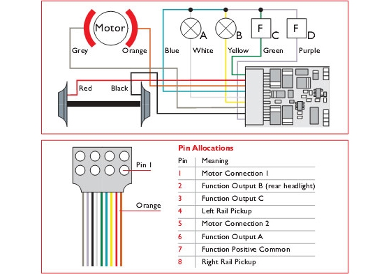
In general, the wiring of each circuit and loco follows the following basic principles.
Decoder Wiring Diagram
-
Remove the plug from the chip.
-
Locate the wires from the pick ups and remove from motor.
-
Solder Black & Red wires from chip, one to each pick up wire.
-
Solder Grey & Orange wires to the motor contacts. There should be no other connections from the pick ups to the motor and any bare wires need to be isolated to prevent short circuits. If the locomotive has lights, follow the colour diagram shown.
-
Locate a suitable decoder position.
-
Make sure all excess wires are bundled up so not to interfere with wheels, gears & valve gears.
-
Test and programme loco to unit.